XL-21 POWER
OVERVIEW
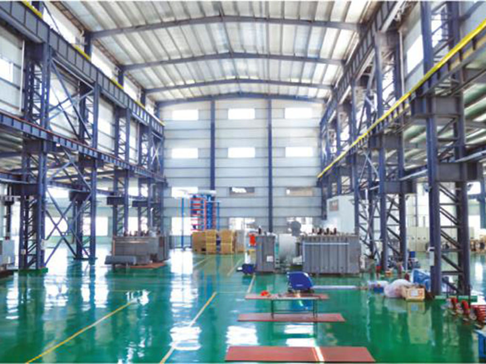
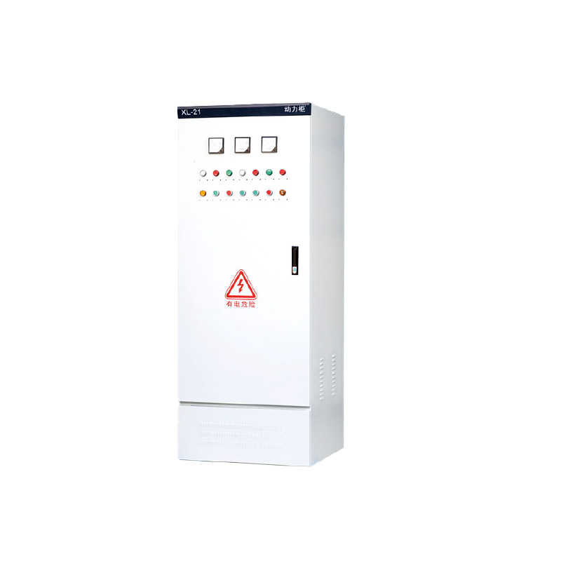
The XL-21 power box is widely used in power plants and industrial and mining enterprises. It is used for power or lighting distribution in distributionsystems with three-phase AC below 500v,including three-phae three wire, three-phase four wire, and three-phase five wire.it is installed indoors aaainsthe wall, operated in front of the screen, and maintained in front of the screen, The box is a fuly enclosed structure, assembled from C profles or 8MFbrofles. The box adopts a new type of rotating load isolation switch, which can be operated with load. The front door is equipped with votage and currentindicating instruments, as wel as siqnallights, butons, conversion switches and other main components. This distibution box adopts self-designed newcomponents.with a compact structure,beautiful andeleaant aoDearanceconvenient maintenance, and multiole wiring schemes for users to choose from.
MODEL AND MEANING
CONDITIONS OF USE
◇ Environmental temperature: -5 ℃ w+40 ℃ , and the average temperature within 24 hours shall not exceed+35 ℃
◇ Altitude: not exceeding 2000m;
◇ Relative humidity: not exceeding 50% when the ambient air temperature is+40'c; At lower temperatures, there can be higher relative humidity (such as90% at+20 ℃℃ ), allowing for moderate condensation due to temperature changes;
◇ During equipment installation, the inclination from the vertical plane should not exceed 5 °.
◇ The equipment should be installed in a place without severe vibration, impact, and corrosion;
Note: When ordering this product beyond the above conditions, please consult with our company.
PRODUCT TECHNICAL FEATURES
◇ The electrical performance fully complies with the relevant provisions of GB 7251.1 and lEC 60439-1;
◇ The feed out switch adopts a new type of molded case circuit breaker and multiple release with smal volume, high breaking, and short (or no) fashover,which has overload and short circuit protection functions and can be equipped with leakage protection functions according to user requirements;
◇ The motor circuit has overload, short circuit, undervoltage, and phase loss protection functions
◇ The auxiliary circuit has local and remote control functions, as well as local and remote automatic switching functions
TECHNICAL PARAMETER
PRECAUTIONS BEFORE INSTALLATION,ACCEPTANCE, AND OPERATION
◇ After the product arives,the first step is to check whether the packaging is intact and undamaged. lf problems are found,relevant departments shouldbe notified in a timely manner to find the cause. For products that are not instaled immediately, they should be placed in an appropriate locationaccording to the requirements of the usage conditions.
◇ The product instalation foundation channel stel and bolts are provided by the use, and the connection holes between the foundation channel steel and the cabinet body;
◇ After installation, the product is inspected and tested before being put into operation
◇ Check if the paint film on the cabinet has fallen off and if the cabinet is dry and clean
◇ Whether the connection and disconnection of main electrical appliances and auxiliary contacts are reliable and accurate
◇ Whether the selection and wiring principle of the main components are consistent with the schematic diagram
◇ Use a 500V megohmmeter with an insulation value not less than 1% 2. When measuring, pay attention to disconnecting and not withstanding voltageor electronic component wiring.
◇ Precautions for use
After multiple opening and closing of low-voltage air circuit breakers, the main contact may be localy burned and carbon like substances may beoroduced,resulting in an increase in contact resistance. Reqular maintenance and repair of universal low-votage ai circuit breakers should be caried outaccordina to their user manual reguirements
TECHNICAL PARAMETER
◇ All models of the product (including the main circuit scheme number and auxiliary circuit scheme number);
◇ Main circuit system diagram and cabinet layout plan;
◇ Electrical schematic diagram of auxiliary circuit;
◇ List of components in the cabinet (specifications of main busbar);
◇ Cabinet color, (if not required, supplied in light camel gray) box size;
◇ Other special reguirements that do not compl with the product's usage conditions shallbe resolved through negotiation with the manufacturer.
MAIN CIRCUIT SCHEME
BOX APPEARANCE AND INSTALLATION DIMENSIONS
Contact with us