GCS LOW VOLTAGEWITHDRAWABLE SWITCHGEAR
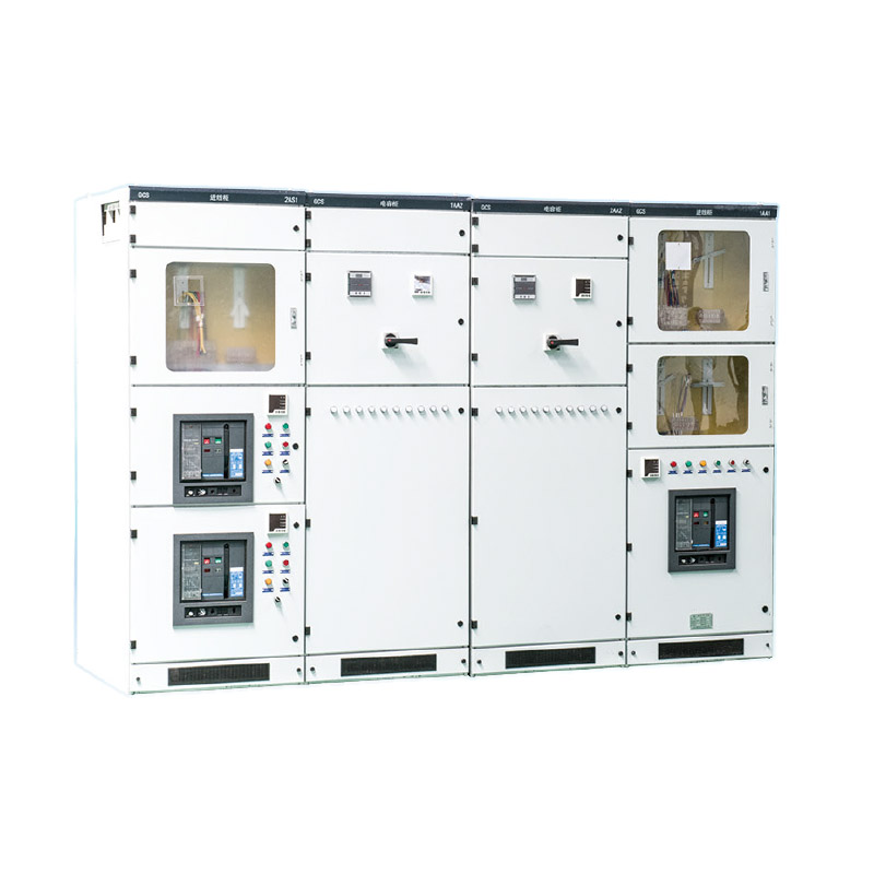
OVERVIEW
GCS low-voltage withdrawable switchgear is suitable for distribution systems in industries such as power plants, petroleum, chemica, metallurgical, textile.and high-rise buildings. in places with high automation levels such as large power plants and petrochemical systems that require computer interfaceslow-votage complete distribution devices are used for distribution, centraized control of electric motors, and reactive power compensation in powergeneration and supply systems with a three-phase Ac frequency of 50 (60) Hz, rated working votage of 380V (400v), (660V, and rated current of 4000A and below.
MODEL AND MEANING
CONDITIONS OF USE
Environmental temperature: not higher than+40 'C and not lower than -5 *c ; The average temperature within 24 hours shall not exceed+35 'c, Whenexceeding, it is necessary to reduce the capacity and operate according to the actual situation;Altitude: not exceeding 2000m, for indoor use:
Atmospheric conditions. The relative humidity of the surounding air should not exceed 50% at the highest temperature of+40'c, and a relatively highrelative humidity is allowed at lower temperatures, such as 90% at+20 'c . lt should be considered that condensation may occur due to temperaturechanges;
When instaling the device, the inclination from the vertical surface should not exced 50*c , and the entire cabinet should be relatively fat (inaccordance with GBJ232-82 standard);
The device should be installed in a place without severe vibration and impact, as well as insuficient to prevent electrical components from beingcorroded as they should be;
Note: When ordering this product beyond the above conditions, please consult with our company.
PERFORMANCE INDEX
The design of the device meets the following standards
◇ IEC439-1 Low voltage switchgear and control equipment;
◇ GB 7251 Low voltage switchgear;
◇ ZBK 36001 low-voltage withdrawable complete switchgear;
BASIC TECHNICAL PARAMETERS
AUXILIARY CIRCUI
The design of the auxiiary circuit diagram complies with relevant design technical regulations such as the "Technical Regulations for Electrical Design ofThermal Power Plants, and is applicable to the low-voltage power system of power plants and substations,as wel as the low-votage distribution systemin factories, mining enterprises, and high-rise buildings.
The auxlary circuit scheme is designed according to the main circuit scheme, which is divided into functional units for power input ine, feeder line (PC) and motor feeder line (MCC) operation control.
MAIN STRUCTURE
The main structure adopts 8MF type open profile stee, with two sides of the profle steel having modules of 20mm, 100mm, and 中 9.2mm mountinghole for flexible and convenient internal installation;
The main frame asembly form is designed into two types, a fully asembled structure and a partially welded structure (side frame and crossbeam),for
users to choose from;
The functional rooms of the device are isolated from each othe, and their compartments are divided into functional unit rooms, busbar rooms, and
cable rooms; The functions of each compartment are relatively independent;The horizontal main busbar is arranged in a horizontal manner behind the cabinet to enhance the abiity of the busbar to withstand electrical forcesand provide high short-circuit strength for the main circuit of the device;
The design of the cable compartment makes it very convenient for cables to enter and exit both up and downThe size series of the universal cabinet of the device (see the table below):

INSTALLATION DIAGRAM


Previous:
MNS LOW VOLTAGE WITHDRAWABLE SWITCHGEAR
Contact with us